
Zhengda Valve
One-Stop Supplier for Rubber Joints, Bellows, and Waterproof Casings
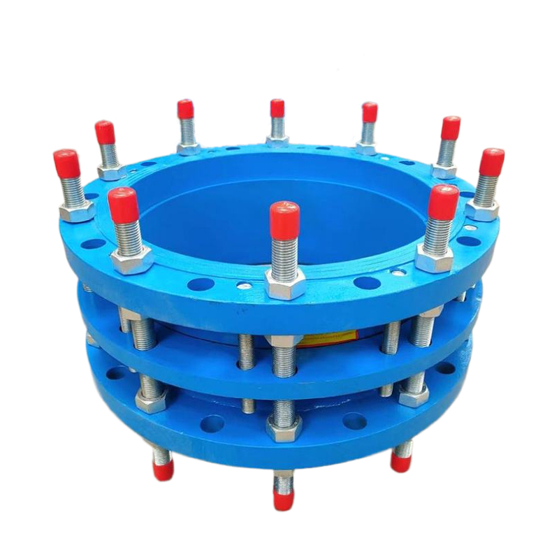

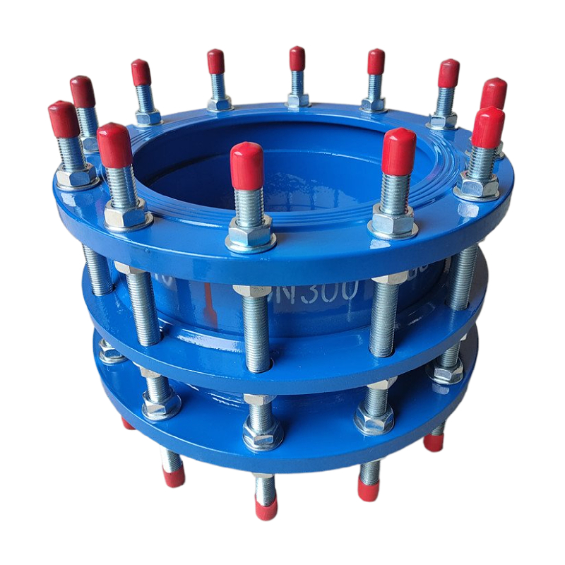
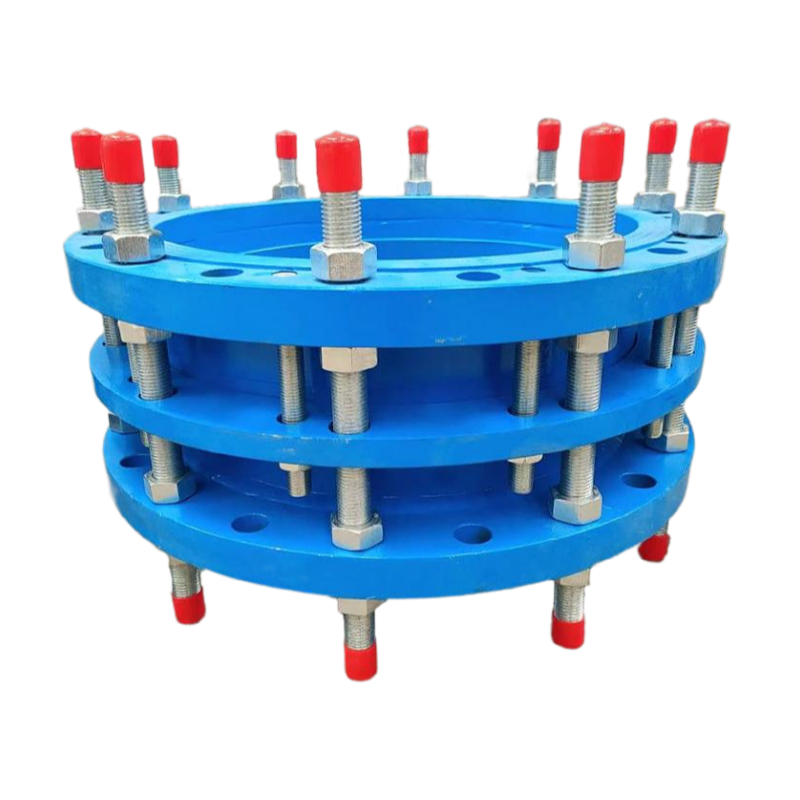
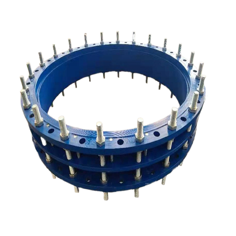
Double Flange Limit Dismantling Joint
Key Features
Technical Specifications
📐 Double-Flange Limited Transmission Joint – Dimensions & Sizes
| Nominal Diameter (DN) | Inch | Length (L) mm | Flange Thickness (b) mm | Bolt Qty (pcs) | Bolt Hole Dia. (mm) | Bolt Circle Dia. (D1) mm | Max Axial Compensation (mm) | Tie Rod Qty (pcs) |
|---|---|---|---|---|---|---|---|---|
| DN50 | 2″ | 260 | 18 | 4 | 18 | 125 | 10 | 2 |
| DN65 | 2.5″ | 280 | 20 | 4 | 18 | 145 | 10 | 2 |
| DN80 | 3″ | 300 | 22 | 8 | 18 | 160 | 12 | 2 |
| DN100 | 4″ | 320 | 24 | 8 | 18 | 180 | 12 | 2 |
| DN125 | 5″ | 340 | 26 | 8 | 18 | 210 | 14 | 2 |
| DN150 | 6″ | 360 | 28 | 8 | 18 | 240 | 14 | 2 |
| DN200 | 8″ | 380 | 30 | 12 | 18 | 295 | 16 | 4 |
| DN250 | 10″ | 410 | 32 | 12 | 18 | 350 | 16 | 4 |
| DN300 | 12″ | 430 | 34 | 12 | 18 | 400 | 18 | 4 |
| DN350 | 14″ | 450 | 36 | 16 | 18 | 460 | 18 | 4 |
| DN400 | 16″ | 470 | 38 | 16 | 18 | 515 | 18 | 6 |
| DN450 | 18″ | 490 | 40 | 20 | 18 | 565 | 20 | 6 |
| DN500 | 20″ | 510 | 42 | 20 | 18 | 620 | 20 | 6 |
| DN600 | 24″ | 550 | 48 | 20 | 18 | 725 | 20 | 8 |
| DN700 | 28″ | 590 | 52 | 24 | 18 | 840 | 20 | 8 |
🔧 Double-Flange Limited Transmission Joint – Technical Parameters
| Parameter | Unit | Specification |
|---|---|---|
| Product Name | – | Double-Flange Limited Transmission Joint |
| Model Code | – | ZD-DLJ (Double Flange with Limit Rods) |
| Nominal Diameter (DN) | mm | DN50 – DN800 |
| Connection Type | – | Flange × Flange |
| Working Pressure (Standard) | MPa / Bar | PN10 (10 bar), PN16 (16 bar), PN25 (25 bar) |
| Shell Pressure Test | MPa | 1.5 × Working Pressure |
| Seal Pressure Test | MPa | 1.1 × Working Pressure |
| Applicable Temperature | °C | -20°C to +200°C |
| Medium Types | – | Potable Water, Industrial Water, Wastewater, Oil, Compressed Air, Weak Acid/Alkali |
| Axial Compensation | mm | ±10 ~ ±20 mm (varies by DN size) |
| Lateral Displacement | mm | 10 ~ 20 mm (typical, depending on model) |
| Angular Deflection | ° | Up to 10° (depending on size & installation) |
| Limit Rods Quantity | pcs | 2 – 8 rods (based on DN) |
| Limit Function | – | Prevents overextension / overcompression caused by internal pressure or vibration |
| Coating | – | Fusion Bonded Epoxy ≥250μm, or Hot-Dip Galvanized |
| Flange Standard | – | GB/T 9115, EN 1092-1, ANSI B16.5, or customer-specified |
| Design Life | Years | 8 – 15 years (under normal use and proper maintenance) |
🧱 Double-Flange Limited Transmission Joint – Materials Specification
| Component | Material Option 1 | Material Option 2 | Remarks / Application Notes |
|---|---|---|---|
| Main Body | Ductile Cast Iron (GGG40 / GGG50) | Carbon Steel (Q235 / Q345) | GGG50: Standard for water systems; Q345: Suitable for industrial & oil systems |
| Flanges | Carbon Steel (Q235B / Q345B) | Stainless Steel (SS304 / SS316) | Conforms to GB, DIN, ANSI, or EN standards |
| Limit Rods | Carbon Steel with Hot-Dip Galvanized | Stainless Steel (SS304 / SS316) | Designed to resist axial displacement under pressure |
| Tie Rod Nuts & Washers | Galvanized Carbon Steel | Stainless Steel | Lock-type or double-nut structure for anti-loosening |
| Bolts & Nuts | Carbon Steel, Zinc-Plated | Stainless Steel (A2-70 / A4-80) | Optional coating: blackening, galvanizing, hot-dip galvanizing |
| Sealing Gasket | EPDM (Ethylene Propylene Diene Rubber) | NBR (Nitrile Rubber) / PTFE | EPDM: For hot water/alkali; NBR: Oil-resistance; PTFE: Acid, solvent, high-temp environment |
| Welded Sleeves | Carbon Steel | Stainless Steel | Internal or external sleeves depend on model design |
| Coating (Internal/External) | Fusion Bonded Epoxy (FBE ≥250μm) | Bitumen / Asphalt Paint / Bare SS | FBE: Default standard; Asphalt for buried pipelines; Stainless steel can be left uncoated |
| Surface Finishing | Shot-blasted to Sa2.5, Coated | Electro-polished (for stainless) | Ensures adhesion of coating and protection from rust or bacteria buildup |
🔍 Material Selection Guidelines
Stainless Steel (SS316) is recommended for marine, food-grade, or chemical plant applications.
Hot-Dip Galvanized Rods are preferred for outdoor and underground installations.
PTFE Gasket must be used when conveying corrosive media (acids, chlorinated water, etc.) or at temperatures above 120°C.
Fusion Bonded Epoxy (FBE) offers >15 years of corrosion protection in potable water systems if properly maintained.
🛠️ Double-Flange Limited Transmission Joint – Installation Guide
| Step | Installation Task | Procedure & Notes |
|---|---|---|
| 1️⃣ | Inspection Before Installation | – Unpack and inspect all components: joint body, flanges, tie rods, bolts, gaskets – Check for visible cracks, deformation, corrosion, or coating damage |
| 2️⃣ | Pipeline Preparation | – Ensure pipeline is clean, properly aligned, and adequately supported – Pipeline ends must be cut square and leveled; flanges must be parallel |
| 3️⃣ | Gasket Placement | – Place suitable gaskets (EPDM/NBR/PTFE) between each flange surface – Gasket must match pressure, medium, and temperature requirements |
| 4️⃣ | Initial Positioning | – Align the joint between the pipe flanges – Insert bolts symmetrically into the flange bolt holes |
| 5️⃣ | Flange Bolt Tightening | – Tighten bolts gradually in star/cross sequence (e.g., 12→6→3→9) to ensure even pressure – Use torque wrench as per standard torque table for each DN size |
| 6️⃣ | Tie Rod Adjustment | – Adjust the limit rods to allow designed axial movement (usually 10–20 mm) – Tighten nuts on both ends to lock axial position |
| 7️⃣ | Double-Nut Locking (Anti-Loosening) | – Use double-nut locking method on tie rods to prevent backspin under vibration – Ensure all tie rods are evenly tensioned and parallel |
| 8️⃣ | Final Alignment Check | – Confirm joint and pipeline flanges are flat and coaxial – Make sure gaskets are not exposed or squeezed out |
| 9️⃣ | Pressure Test | – Perform hydrostatic test at 1.5× working pressure or as required – Check for leaks around flanges and adjust bolts if necessary |
| 🔟 | Commissioning | – Once test passed, slowly bring the pipeline into service – Observe for at least 30 minutes during initial pressurization |
⚠️ Special Notes for Limited Joints:
Do not use tie rods to forcibly pull pipes into alignment – this can damage both the joint and pipeline.
Do not weld near the joint after installation.
For buried applications, coat tie rods with corrosion-resistant wrap or bitumen.
Use pipe supports or brackets near joints to reduce axial force.
🧰 Double-Flange Limited Transmission Joint – Maintenance Guide
| Maintenance Task | Recommended Frequency | Procedure & Notes | Purpose / Effect |
|---|---|---|---|
| 🔎 Visual Inspection | Monthly / Quarterly | – Check for flange leakage, rust on tie rods, or deformation – Observe paint/coating condition | Detect early signs of damage or degradation |
| 🔧 Bolt & Tie Rod Torque Check | Every 6 months | – Use torque wrench to re-tighten all flange bolts and tie rod nuts – Follow original cross-tightening pattern | Prevent loosening due to thermal stress or vibration |
| 🧪 Gasket Integrity Check | Every 6–12 months | – Check for hardening, cracks, swelling, or extrusion of the gasket – Replace if any sign of wear | Ensures continuous sealing performance |
| 🧹 Surface Cleaning | Every 6–12 months | – Remove dirt, mud, corrosion from surface – Recoat or touch-up fusion bonded epoxy if necessary | Preserves anti-corrosion properties and visual condition |
| 🔩 Limit Rod Inspection | Annually | – Check tie rods for corrosion, bend, or thread damage – Verify lock nuts are intact and tight | Guarantees mechanical limit functionality and axial force containment |
| ♻️ Coating Maintenance | Annually / As Needed | – Touch up chipped epoxy or repaint tie rods – For underground use, inspect protective wrap or bitumen coverage | Prolongs lifespan and prevents hidden corrosion |
| 🔁 Component Replacement | Every 3–5 years | – Replace tie rods, bolts, or gaskets if signs of wear appear – Use original or equivalent material grade | Avoid fatigue failures in high-pressure or fluctuating systems |
| 🧾 Maintenance Record Logging | During each inspection | – Record torque values, component condition, replacements, and date – Include inspector name and comments | Enables traceability and preventive maintenance planning |
⚠️ Failure Symptoms & Recommended Actions
| Observed Issue | Possible Cause | Corrective Action |
|---|---|---|
| Flange leakage | Gasket aging or under-tightened bolts | Retighten bolts or replace gasket |
| Tie rods bent or broken | Excessive thrust or poor alignment | Replace rods, check axial installation error |
| Rods rusted or threads stripped | Poor coating / exposure to moisture | Replace rods, apply anti-rust coating or use stainless steel rods |
| Gasket extruded or squeezed out | Overpressure or incompatible gasket material | Replace with suitable high-pressure gasket (e.g., PTFE) |
| Epoxy coating peeling | UV exposure or buried acid soil | Recoat surface with FBE or asphalt-based coating |
What is a Double Flange Dismantling Joint with Limit Rods used for?
It is designed to compensate for limited axial movement while protecting pipelines from overextension. The integrated limit rods prevent separation caused by internal pressure or surge forces, making it ideal for pressurized pipeline systems like water supply, HVAC, and fire protection networks.
What sizes and materials are available for this type of dismantling joint?
Our double flange limit joint is available in DN65 to DN2000, made from ductile iron or carbon steel with epoxy coating. Limit rods are offered in galvanized or stainless steel, ensuring corrosion resistance and long service life.
Can the limit rods be adjusted or customized?
Yes, the limit rods can be tailored to specific thrust requirements. We offer adjustable rod lengths, reinforced structures, and optional anti-loosening nuts to match custom specifications or system pressures.
How does this joint simplify pipeline installation and maintenance?
The dismantling structure allows for quick disassembly of valves, pumps, or fittings without moving the entire pipeline. It saves labor and time during installation or repair, especially in confined spaces or buried pipelines.
Let Us Help With Your Pipeline Needs
Contact Us Now
Let Us Help With Your Pipeline Needs
We respond quickly to inquiries and provide expert support on rubber joints, metal hoses, and customized solutions.