
Zhengda Valve
One-Stop Supplier for Rubber Joints, Bellows, and Waterproof Casings
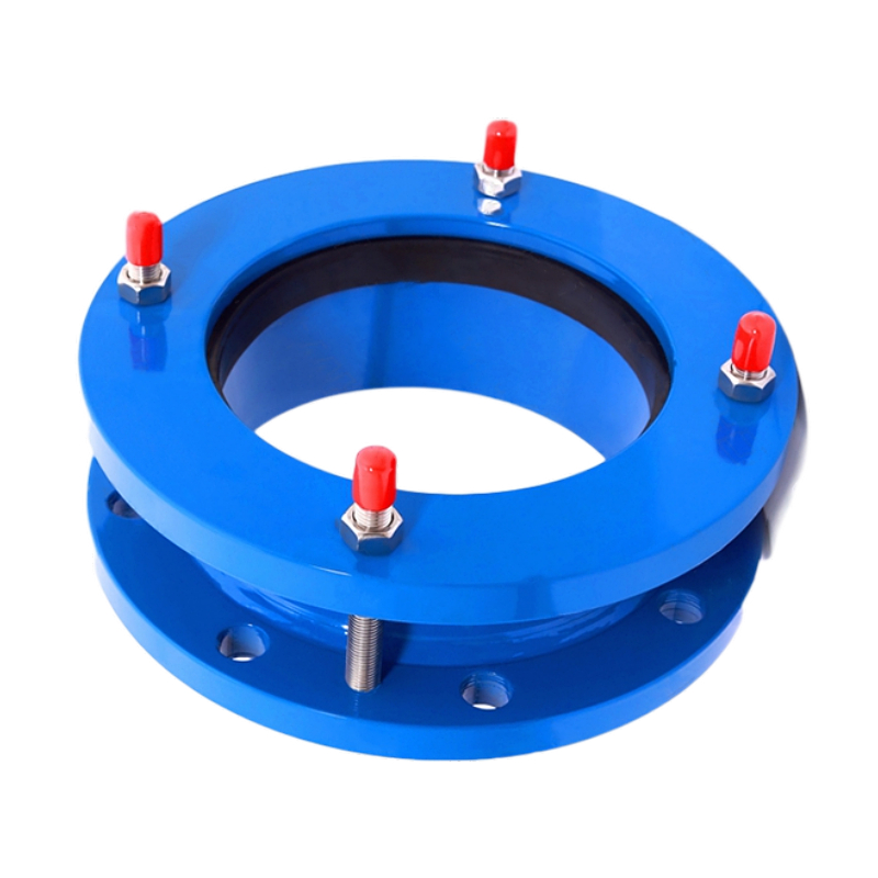
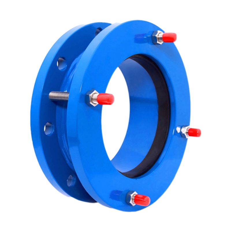
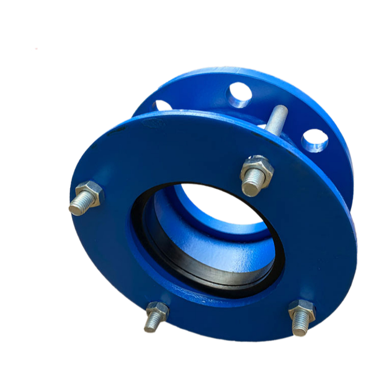
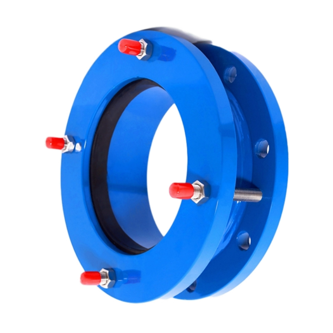
Loose Sleeve Flanged Dismantling Joint
Flanged Loose Sleeve Joint with Limit Rods is a versatile pipeline connection device designed to provide axial flexibility and controlled expansion while effectively transmitting thrust force between connected pipelines. Equipped with limit rods (tie rods), this joint prevents pipeline separation caused by internal pressure or ground movement, making it ideal for high-pressure and long-distance pipeline systems.
This type of joint features a flanged end and a loose (movable) sleeve structure, allowing for easy installation, disassembly, and precise alignment of piping systems. It is commonly used in water supply systems, fire protection networks, HVAC pipelines, industrial sewage systems, and petrochemical installations.
Key Features
Technical Specifications
📐 Flanged Loose Sleeve Joint – Dimensions & Sizes
| Nominal Diameter (DN) | Inch | Length (L) mm | Flange Thickness (b) mm | Bolt Qty (pcs) | Bolt Hole Dia. (mm) | Bolt Circle Dia. (D1) mm | Axial Expansion Range (mm) |
|---|---|---|---|---|---|---|---|
| DN50 | 2″ | 130 | 18 | 4 | 18 | 125 | 10 |
| DN65 | 2.5″ | 135 | 20 | 4 | 18 | 145 | 10 |
| DN80 | 3″ | 145 | 22 | 8 | 18 | 160 | 12 |
| DN100 | 4″ | 155 | 24 | 8 | 18 | 180 | 12 |
| DN125 | 5″ | 165 | 26 | 8 | 18 | 210 | 14 |
| DN150 | 6″ | 175 | 28 | 8 | 18 | 240 | 14 |
| DN200 | 8″ | 190 | 30 | 12 | 18 | 295 | 16 |
| DN250 | 10″ | 210 | 32 | 12 | 18 | 350 | 16 |
| DN300 | 12″ | 230 | 34 | 12 | 18 | 400 | 18 |
| DN350 | 14″ | 250 | 36 | 16 | 18 | 460 | 18 |
| DN400 | 16″ | 270 | 38 | 16 | 18 | 515 | 18 |
| DN450 | 18″ | 290 | 40 | 20 | 18 | 565 | 20 |
| DN500 | 20″ | 310 | 42 | 20 | 18 | 620 | 20 |
| DN600 | 24″ | 330 | 48 | 20 | 18 | 725 | 20 |
🔧 Flanged Loose Sleeve Joint – Technical Parameters
| Parameter | Unit | Specification |
|---|---|---|
| Product Name | – | Flanged Loose Sleeve Joint |
| Model Code | – | ZD-FLJ (Flange Loose Joint, No Tie Rods) |
| Nominal Diameter Range | mm | DN50 – DN600 |
| Connection Type | – | Flange × Flange |
| Working Pressure | MPa / Bar | PN10 (10 bar), PN16 (16 bar), PN25 (25 bar) |
| Shell Test Pressure | MPa | 1.5 × Working Pressure |
| Seal Test Pressure | MPa | 1.1 × Working Pressure |
| Applicable Temperature | °C | -20°C to +200°C (Depending on gasket material) |
| Applicable Medium | – | Water, Wastewater, Oil, Gas, Compressed Air, Weak Acid & Alkali |
| Axial Expansion Capability | mm | 10 – 20 mm (based on diameter) |
| Angular Deflection (max) | ° | 8° – 12° |
| Lateral Displacement (max) | mm | Up to 20 mm |
| Connection Standard | – | GB/T 9115, ISO 7005, EN 1092, ANSI B16.5 (customizable) |
| Sealing Performance | – | No visible leakage under working pressure |
| Internal Structure | – | Sleeve type telescopic structure with compression gasket sealing |
| Design Life (Recommended) | Years | 8 – 15 Years (with proper maintenance and within pressure/temperature limits) |
| Installation Location | – | Aboveground, Indoor, Outdoor, Not recommended for buried use unless protected |
🧱 Flanged Loose Sleeve Joint – Materials Specification
| Component | Material Option 1 | Material Option 2 | Application & Notes |
|---|---|---|---|
| Main Body | Ductile Cast Iron (GGG40 / GGG50) | Carbon Steel (Q235 / Q345) | GGG50: Suitable for water, heating, and municipal applications; Q345: for industrial use |
| Loose Flange Ends | Carbon Steel (Q235B / Q345B) | Stainless Steel (SS304 / SS316) | Flanges drilled per GB, DIN, ANSI, or EN standards |
| Sleeve Section | Carbon Steel | Stainless Steel | The sliding or telescopic section that accommodates axial movement |
| Sealing Gasket | EPDM (Ethylene Propylene Rubber) | NBR (Nitrile Rubber) / PTFE | EPDM: Water, hot water, alkaline; NBR: Oil, fuel; PTFE: Chemicals, acids, solvents |
| Bolts & Nuts | Carbon Steel, Zinc-Plated | Stainless Steel (A2-70 / A4-80) | Use appropriate strength class (e.g., 8.8) for pressure applications |
| Washer / Spacer Ring | Carbon Steel with Zinc Coating | Stainless Steel | Helps evenly distribute pressure around the sealing surface |
| Coating | Fusion Bonded Epoxy (≥250μm) | Bitumen Paint / Bare Stainless Finish | Epoxy is standard; bitumen for underground; stainless may be uncoated if polished |
| Surface Finish | Shot-blasted to Sa2.5, coated | Polished & Passivated (for SS) | Shot-blasting improves adhesion; passivation improves corrosion resistance |
🔍 Material Selection Recommendations
Ductile Iron (GGG50) is the most cost-effective and widely used for civil water systems.
Carbon Steel (Q345) is recommended for general industrial pipelines under high strength requirements.
Stainless Steel (SS316) is ideal for chemical plants, coastal, marine, or food-grade applications.
PTFE Gaskets should be used for corrosive or high-temperature media above 120°C.
Fusion Bonded Epoxy (FBE) provides 15–20 years of corrosion protection in potable water lines if undamaged.
🛠️ Flanged Loose Sleeve Joint – Installation Guide
| Step | Installation Task | Detailed Procedure & Notes |
|---|---|---|
| 1️⃣ | Inspection Before Installation | – Unpack all components and inspect the joint body, sealing surfaces, flanges, and sleeve – Ensure no deformation, rust, or transport damage |
| 2️⃣ | Pipeline End Preparation | – Pipe ends must be flat, clean, burr-free, and cut perpendicular to the axis – Verify axial alignment and that there is sufficient straight pipe on both sides |
| 3️⃣ | Positioning the Joint | – Insert the loose sleeve joint between two pipeline flanges – Ensure the flanges match the bolt hole pattern and pressure rating |
| 4️⃣ | Gasket Placement | – Place the correct gasket (EPDM/NBR/PTFE) between each flange face – Center the gasket carefully to avoid displacement during tightening |
| 5️⃣ | Bolt Assembly | – Insert flange bolts symmetrically and tighten in a star pattern (e.g. 12→6→3→9…) – Do not fully tighten one side before the other |
| 6️⃣ | Axial Adjustment | – If minor misalignment or expansion space is needed, adjust the sleeve position within its allowable axial range (usually 10–20 mm) |
| 7️⃣ | Final Torque Application | – Use a calibrated torque wrench to tighten bolts according to torque tables (varies by DN and pressure) – Ensure even compression of the gasket |
| 8️⃣ | Sealing Check | – Confirm gasket is not visible outside the flange connection and that no uneven gaps exist |
| 9️⃣ | Pressure Testing | – Conduct hydrostatic or pneumatic pressure testing per standard – Monitor for any leakage at flange faces and around gasket area |
| 🔟 | Commissioning | – After successful testing, slowly pressurize the line and bring the system into operation |
⚠️ Important Installation Tips
| Topic | Best Practice |
|---|---|
| Gasket Selection | Always match gasket to the medium (e.g. EPDM for water, PTFE for chemicals) |
| Alignment Tolerance | Allowable misalignment < 2 mm and angular deflection < 3° |
| Do Not Use as Load Bearing | Joint should not bear pipe weight—use proper pipe supports |
| No Tie Rods Included | This joint type does not include limit rods—not suitable for thrust restraint |
| Underground Installation | Apply additional bitumen or PE wrapping for buried service |
🧰 Flanged Loose Sleeve Joint – Maintenance Guide
| Maintenance Task | Recommended Frequency | Detailed Procedure & Notes | Purpose / Effect |
|---|---|---|---|
| 🔍 Visual Inspection | Monthly / Quarterly | – Check for signs of leakage, flange rust, or sleeve misalignment – Inspect flange coating or paint condition | Detect early corrosion, deformation, or potential failure |
| 🔧 Bolt Tightness Check | Every 3–6 months | – Use torque wrench to verify flange bolts are still within specified torque – Tighten in cross-pattern if needed | Prevent gasket relaxation or leakage due to vibration or thermal cycling |
| 🧪 Seal/Gasket Condition Check | Every 6–12 months | – Check for aging signs: hardening, cracks, swelling, extrusion – Replace with identical size and material if necessary | Ensure reliable sealing and prevent unplanned shutdowns |
| 🧱 Sleeve Movement Check | Annually | – Confirm the sleeve still has axial flexibility within rated range – No rust jamming or overcompression signs | Ensure continued ability to absorb expansion or misalignment |
| 🧴 Surface Protection Maintenance | Annually | – Remove surface dust, reapply fusion bonded epoxy or corrosion protection paint if damaged – Touch up damaged areas | Maintain corrosion resistance and extend product lifespan |
| 🔁 Bolt/Nut Replacement | Every 3–5 years | – Replace bolts/nuts if threads are rusted or stripped – Use matching material and grade (e.g. A2-70, 8.8 class) | Maintain mechanical integrity and flange strength |
| 🧾 Maintenance Logging | Every inspection | – Record date, observations, actions taken, and part replacements – Include technician name and photos if possible | Establish service history and support future troubleshooting |
⚠️ Common Failure Symptoms & Solutions
| Symptom | Likely Cause | Recommended Action |
|---|---|---|
| Flange leakage | Gasket wear or under-tightened bolts | Replace gasket, re-torque all bolts |
| Gasket extrusion | Overcompression or pressure surge | Install correct gasket thickness, inspect pressure control |
| Rust on sleeve or bolts | Damaged coating or humid environment | Clean surface, repaint, or upgrade to stainless bolts |
| No axial movement | Internal rust binding sleeve | Disassemble, clean, grease, or replace |
| Flange misalignment | Pipe settlement or thermal distortion | Re-align pipeline supports, reinstall joint if necessary |
✅ Recommended Spare Parts
Rubber Gaskets (EPDM, NBR, or PTFE) – matched to pressure and media
Full sets of Flange Bolts & Nuts
Sleeve Section (if replaceable type)
🔹 What is a Flanged Loose Sleeve Joint with Limit Rods used for?
This joint is used to connect pipelines while allowing limited axial movement.
The limit rods prevent pipe separation caused by internal pressure or vibration. It is widely used in water supply, wastewater, HVAC, and fire protection systems.
🔹 Can the joint compensate for pipeline installation misalignment?
Yes.
The loose sleeve design allows slight axial adjustment and misalignment compensation during installation, reducing pipeline stress and ensuring a better seal.
🔹 What sizes and pressure ratings are available?
We offer a full range of standard sizes from DN50 to DN1600,
with pressure ratings from PN10 to PN25. Custom sizes and materials are also available upon request.
🔹 What are the main materials used for this joint?
The body is typically made of ductile iron or carbon steel with epoxy coating,
while the bolts and limit rods use galvanized or stainless steel. All materials comply with international standards for durability and corrosion resistance.
Let Us Help With Your Pipeline Needs
Contact Us Now
Let Us Help With Your Pipeline Needs
We respond quickly to inquiries and provide expert support on rubber joints, metal hoses, and customized solutions.