
Zhengda Valve
One-Stop Supplier for Rubber Joints, Bellows, and Waterproof Casings
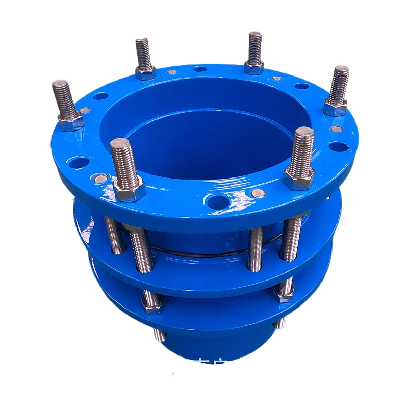
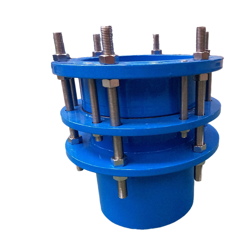
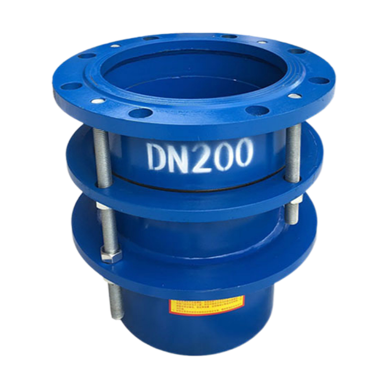
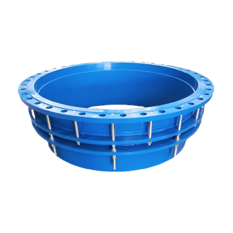
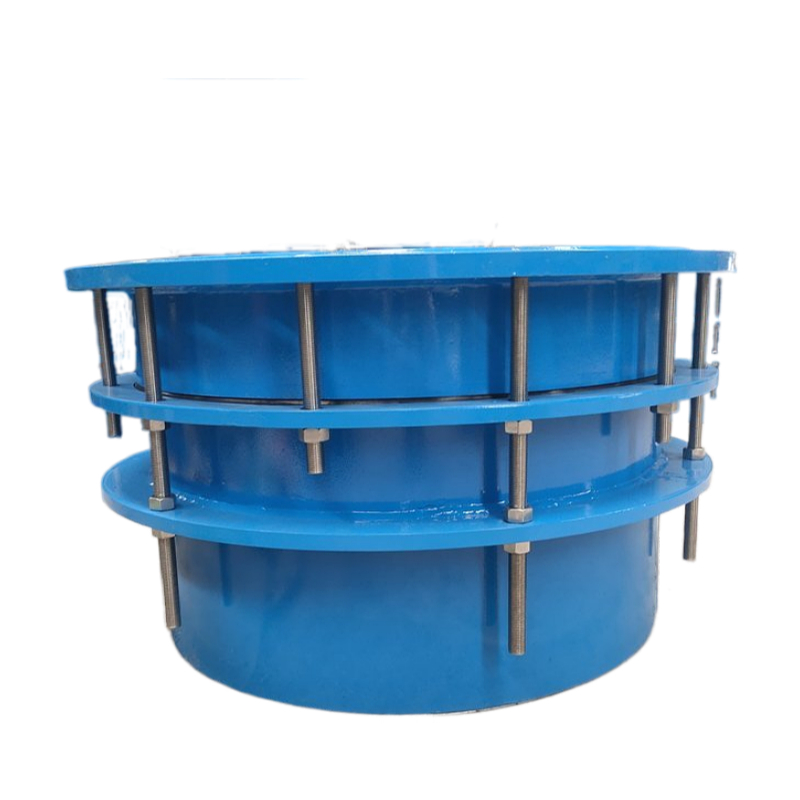
Single-Flange Dismantling Joint
The Single Flange Dismantling Joint, also known as a Single Flange Force Transmission Joint, is a specialized pipe fitting designed to facilitate easy installation and removal of valves, pumps, and other pipeline components. Featuring a flanged end on one side and a welded, sliding sleeve structure on the other, this joint allows for axial adjustment, absorbs pipeline stress, and provides secure transmission of thrust force between pipeline sections.
This type of dismantling joint is commonly used in water supply systems, municipal infrastructure, HVAC networks, industrial fluid handling, and fire protection systems, where pipeline misalignment and thermal expansion need to be managed safely and efficiently. The robust construction and high-performance sealing of this product make it suitable for both above-ground and buried pipeline applications.
With easy disassembly, the Single Flange Dismantling Joint is ideal for systems requiring regular maintenance or tight installation spaces. It is manufactured according to EN1092-1, GB/T, or ANSI flange standards and is compatible with PN10, PN16, and PN25 pressure classes.
Key Features
Technical Specifications
| Nominal Diameter (DN) | Inch | Length (L) mm | Flange Thickness (b) mm | Bolt Qty (n) | Bolt Hole Dia. mm | Bolt Circle Dia. (D1) mm | Axial Extension mm | Lateral Displacement mm | Angular Deflection (°) |
|---|---|---|---|---|---|---|---|---|---|
| DN32 | 1.25″ | 95 | 16 | 4 | 18 | 100 | 6 | 9 | 9 |
| DN40 | 1.5″ | 95 | 18 | 4 | 18 | 110 | 6 | 10 | 9 |
| DN50 | 2″ | 105 | 18 | 4 | 18 | 125 | 7 | 10 | 10 |
| DN65 | 2.5″ | 115 | 20 | 4 | 18 | 145 | 7 | 13 | 11 |
| DN80 | 3″ | 135 | 22 | 8 | 18 | 160 | 8 | 15 | 12 |
| DN100 | 4″ | 150 | 24 | 8 | 18 | 180 | 9 | 15 | 12 |
| DN125 | 5″ | 165 | 26 | 8 | 18 | 210 | 9 | 16 | 12 |
| DN150 | 6″ | 180 | 26 | 8 | 18 | 240 | 10 | 18 | 12 |
| DN200 | 8″ | 195 | 28 | 8 | 18 | 295 | 10 | 18 | 12 |
| DN250 | 10″ | 225 | 30 | 12 | 18 | 350 | 11 | 20 | 10 |
| DN300 | 12″ | 255 | 32 | 12 | 18 | 400 | 12 | 22 | 10 |
| DN350 | 14″ | 285 | 34 | 16 | 18 | 460 | 12 | 22 | 9 |
| DN400 | 16″ | 315 | 36 | 16 | 18 | 515 | 12 | 22 | 9 |
| DN450 | 18″ | 345 | 38 | 20 | 18 | 565 | 12 | 22 | 8 |
| DN500 | 20″ | 375 | 40 | 20 | 18 | 620 | 12 | 22 | 8 |
🔧 Single-Flange Transmission Joint – Technical Parameters
| Parameter | Unit | Specification |
|---|---|---|
| Product Model | – | ZD-SFJ (Single Flange Joint) |
| Working Pressure | MPa / bar | 1.0 / 10, 1.6 / 16, 2.5 / 25 (Optional) |
| Test Pressure (Shell) | MPa | 1.5 × Working Pressure |
| Test Pressure (Sealing) | MPa | 1.1 × Working Pressure |
| Max. Axial Compensation | mm | ±10 ~ ±35 (varies by DN size) |
| Max. Lateral Compensation | mm | 5 ~ 25 mm |
| Max. Angular Deflection | ° | 8° ~ 12° |
| Applicable Temperature Range | °C | -20°C ~ +200°C |
| Sealing Performance | – | Zero leakage under rated pressure |
| Connection Method | – | One side flange connection, one side welding or socket |
| Installation Medium | – | Potable Water, Wastewater, Gas, Oil, Acid & Alkali |
| Standard Compliance | – | GB/T 12465, EN 1092, ISO 7005, ANSI B16.5 |
🧱 Single-Flange Transmission Joint – Materials Specification
| Component | Material Options | Notes |
|---|---|---|
| Main Body | Ductile Iron (GGG40 / GGG50) | Standard, good strength, corrosion resistance |
| Carbon Steel (Q235 / Q345) | Suitable for industrial pipelines, economic solution | |
| Stainless Steel (SS304 / SS316) | For corrosive environments such as chemicals, seawater, acid media | |
| Flange End | Carbon Steel (Q235 / Q345) | Flange dimensions conform to GB, ANSI, DIN, or customized |
| Stainless Steel (SS304 / SS316) | Used in high corrosion or food-grade applications | |
| Sealing Gasket | NBR (Nitrile Rubber) | Oil-resistant, suitable for petroleum-based media |
| EPDM (Ethylene Propylene Diene Rubber) | Excellent for water, steam, acid & alkali resistance | |
| PTFE (Polytetrafluoroethylene / Teflon) | Chemically inert, high temperature and strong acid/base environments | |
| Tie Rods / Bolts | Carbon Steel, Zinc Plated | Standard type, corrosion protected |
| Hot-Dip Galvanized Steel | Improved corrosion resistance | |
| Stainless Steel (SS304 / SS316) | High corrosion resistance, long service life | |
| Surface Coating | Fusion Bonded Epoxy (≥250 μm) | Standard anti-corrosion internal & external coating |
| Bitumen / Asphalt Coating | For underground applications | |
| Galvanization or Natural Stainless Finish | Depending on material selection |
🛠️ Single-Flange Transmission Joint – Installation Guide
✅ 1. Pre-Installation Preparation
Inspect Components: Ensure that all parts (body, flange, bolts, gaskets) are complete and free from damage, rust, or debris.
Check Compatibility: Confirm the joint size (DN), pressure rating, and flange standard match the pipeline specifications.
Clean Connection Surfaces: Ensure the flange faces and pipeline ends are flat, clean, and free of oil, rust, or burrs.
🔧 2. Installation Procedure
Step 1: Positioning
Insert the welded or socket end of the joint into the corresponding pipeline.
Align the flange face of the joint with the pipeline flange.
Step 2: Gasket Placement
Place a gasket (NBR, EPDM, or PTFE) between the flanges. Center the gasket precisely to avoid displacement during bolting.
Step 3: Bolt Installation
Insert bolts through the flange holes and tighten the nuts gradually.
Use a cross-tightening pattern (e.g., 12 o’clock → 6 o’clock → 3 o’clock → 9 o’clock) to ensure uniform pressure.
Use a torque wrench to follow manufacturer-recommended torque values.
Step 4: Axial Adjustment
Adjust the telescopic end of the joint to compensate for misalignment or expansion.
Fix the axial length before final tightening of the locking bolts (if equipped).
Step 5: Final Check
Verify that all bolts are evenly tightened and the gasket is properly seated.
Ensure the joint is not under excessive bending, twisting, or pulling force.
⚠️ 3. Installation Precautions
Do not use the joint to forcibly correct pipeline misalignment.
Do not weld or cut any part of the joint after installation.
Avoid over-tightening bolts to prevent deformation of the sealing surface.
Install support brackets if the pipeline is long or heavy to reduce axial load.
🧪 4. Pressure Testing
After installation, conduct a hydrostatic or pneumatic pressure test.
Monitor for leaks at the flange face and around the gasket.
Retighten bolts if necessary, following the cross-pattern sequence.
🧰 Single-Flange Transmission Joint – Maintenance Guide
🔍 1. Routine Maintenance (Monthly / Quarterly)
Visual Inspection:
Check for surface corrosion, rust, or damage on the flange, bolts, and body.
Look for signs of leakage around the gasket area.
Bolt Tightness Check:
Use a torque wrench to ensure all bolts maintain the proper torque.
Tighten bolts in a cross-pattern if loosening is detected.
Gasket Observation:
If there is minor leakage, the gasket may be aged or misaligned. Plan for replacement.
🛠️ 2. Annual Maintenance Checklist
Disassembly & Cleaning (if required):
Shut down the system and release pressure before removing the joint.
Clean internal surfaces to remove sediment, rust, or scale.
Inspect the sealing surface for scratches or wear. Smooth out minor defects with appropriate tools.
Gasket Replacement:
Replace the gasket if hardened, cracked, or deformed.
Ensure the new gasket is compatible with the conveyed medium and temperature.
Coating Inspection:
Check the internal and external anti-corrosion coating.
Touch-up epoxy or reapply paint if peeling or damage is found.
Reassembly:
Reinstall the joint following the standard installation guide.
Conduct pressure testing before resuming operation.
🔒 3. Long-Term Reliability Measures
Service Life Monitoring:
Maintain a logbook of installation date, material batch, and service condition.
Replace the joint if it exceeds the recommended service life (typically 8–15 years depending on medium and environment).
Environmental Consideration:
For buried pipelines, inspect the joint chamber for flooding or water retention.
Ensure cathodic protection systems (if any) are functioning for underground metallic pipelines.
Torque Recheck Frequency:
In high-pressure or high-vibration environments, recheck bolt torque every 3–6 months.
⚠️ 4. Replacement Criteria
Severe corrosion on flanges or bolts
Irrecoverable deformation of the joint body
Persistent leakage despite re-tightening
Gasket completely hardened, cracked, or melted
What is a Single Flange Dismantling Joint used for?
A Single Flange Dismantling Joint is used to connect valves, pumps, and pipes in pressure pipeline systems. It allows for easy installation and disassembly while transmitting axial thrust and absorbing pipe movement.
What sizes and pressure ratings are available?
Our single flange dismantling joints are available in sizes from DN50 to DN1600, and pressure ratings PN10, PN16, and PN25. Custom diameters and pressure ratings are available upon request.
Can I customize the structure or coating of the joint?
Yes. We offer OEM/ODM services for flange dimensions, length, coating color (FBE, epoxy), and bolt materials (carbon steel, stainless steel). Our technical team will assist with drawings and recommendations.
What are the main materials used in your dismantling joints?
The body is made from ductile iron or carbon steel. Flanges are drilled to DIN, ANSI, or BS standards. Bolts are zinc-plated or stainless steel, and rubber gaskets are EPDM or NBR, depending on working conditions.
Let Us Help With Your Pipeline Needs
Contact Us Now
Let Us Help With Your Pipeline Needs
We respond quickly to inquiries and provide expert support on rubber joints, metal hoses, and customized solutions.